FORCED CIRCULATIONFOOD CONCENTRATION SYSTEMS

Home / Project engineering

Forced-circulation equipment and system modules

Review eight equipment duties, their connections, specification inputs and maintenance requirements.

Equipment directory

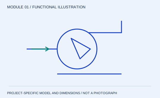
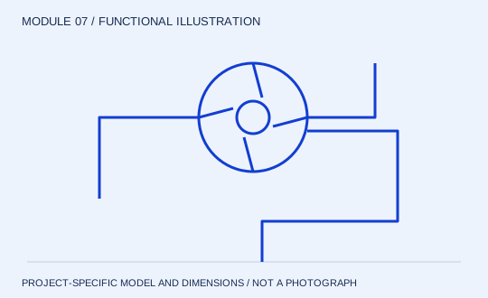
Circulation pump & drive functional diagram
MODULE 01

Circulation pump & drive

Keep the loop moving. The circulation pump sets the flow through the heater. That flow is distinct from the incoming feed and from the mass of water evaporated. Selection must follow the concentrated liquid throughout the planned operating range, including start-up and restart after cooling.

Review structure & specification →
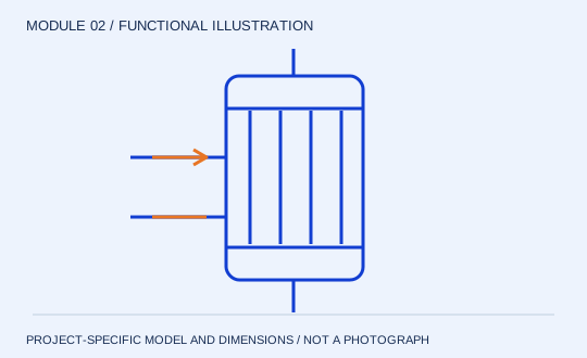
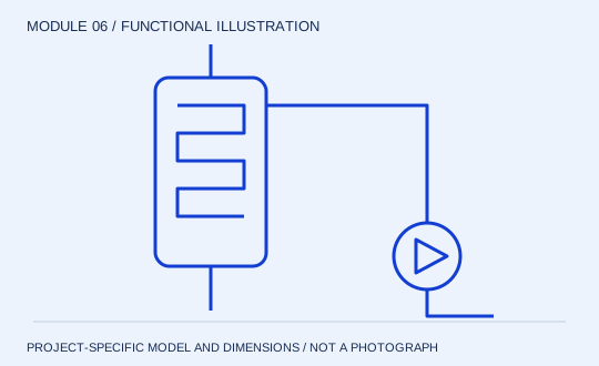
External heater functional diagram
MODULE 02

External heater

Add heat under pressure. In the common non-boiling heater arrangement, pressure in the circuit limits boiling within the heater. Heat is added before the liquid enters the flash zone. Tube or plate geometry is selected from product behaviour and pressure-drop constraints, rather than the circulation label alone.

Review structure & specification →
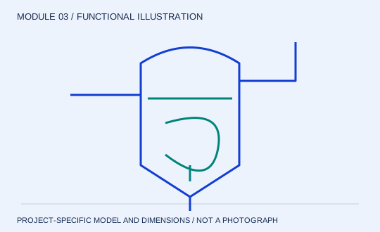
Flash separation vessel functional diagram
MODULE 03

Flash separation vessel

Release vapour and retain liquid. The pressure change at the separator enables part of the heated liquid to flash. The vessel provides space for vapour disengagement while maintaining liquid inventory for recirculation. Its level and geometry therefore affect both separation and pump suction.

Review structure & specification →
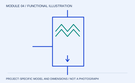
Entrainment separation functional diagram
MODULE 04

Entrainment separation

Protect the recovered vapour. Droplets leaving with the vapour represent product loss and can contaminate downstream equipment. A separation device must work with the product’s foam and fouling behaviour. The choice of internals depends on the operating envelope and cleaning access.

Review structure & specification →
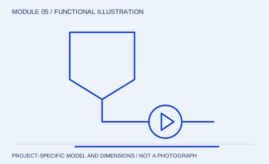
Concentrate discharge package functional diagram
MODULE 05

Concentrate discharge package

Control the product leaving the loop. Withdrawal and fresh feed must remain consistent with the water-removal duty and circulating inventory. The discharge equipment is selected for final concentrate properties, which may differ substantially from feed properties.

Review structure & specification →
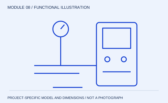
Controls, sampling & CIP interfaces functional diagram
MODULE 08

Controls, sampling & CIP interfaces

Observe the limits; validate the clean. A useful control philosophy connects each process risk to a measurement and response. Loss of circulation, feed interruption or a changing vacuum needs a defined action. The cleaning boundary must include the pump and every product-contact part of the loop.

Review structure & specification →

Request the evidence for the proposed model

Ask for identified equipment photographs, model drawings, rated duty, material selection and acceptance conditions with the project proposal. The illustrations here explain circuit functions and do not claim a delivered plant or a verified model.

Discuss this concentration duty