FORCED CIRCULATIONFOOD CONCENTRATION SYSTEMS

Home / Systems

TVR forced circulation evaporator system

Assess thermal vapour recompression against available motive steam, process vapour conditions, heating duty and the intended operating range.

Define the motive-steam interface

Thermal vapour recompression uses motive steam to entrain process vapour and supply a heating mixture. State the available steam pressure and condition together with the suction and discharge conditions. A TVR label alone is not a utility specification.

Keep circulation and recompression separate

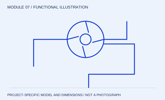
The liquid circulation loop still needs its own flow, pressure-drop and pump selection. Compare the steam supply, reused vapour and net evaporation at the same product duty. Agree which utilities and auxiliary equipment are included in the quotation.

Review the operating envelope

Discuss how steam variation, changing evaporation load and product concentration affect operation. Request the proposed control arrangement and start-up sequence, plus an acceptance basis that states the measured utility and product conditions.

Information to include in your enquiry

  • Motive steam pressure and condition
  • Process vapour suction condition
  • Heating duty and evaporation load
  • Expected operating range

Equipment to review together

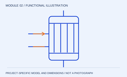
External heater functional diagram
MODULE 02

External heater

Add heat under pressure. In the common non-boiling heater arrangement, pressure in the circuit limits boiling within the heater. Heat is added before the liquid enters the flash zone. Tube or plate geometry is selected from product behaviour and pressure-drop constraints, rather than the circulation label alone.

Review structure & specification →
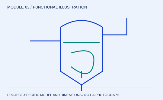
Flash separation vessel functional diagram
MODULE 03

Flash separation vessel

Release vapour and retain liquid. The pressure change at the separator enables part of the heated liquid to flash. The vessel provides space for vapour disengagement while maintaining liquid inventory for recirculation. Its level and geometry therefore affect both separation and pump suction.

Review structure & specification →
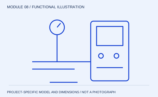
Controls, sampling & CIP interfaces functional diagram
MODULE 08

Controls, sampling & CIP interfaces

Observe the limits; validate the clean. A useful control philosophy connects each process risk to a measurement and response. Loss of circulation, feed interruption or a changing vacuum needs a defined action. The cleaning boundary must include the pump and every product-contact part of the loop.

Review structure & specification →