Home / Project engineering
Circulation pump & drive for forced-circulation evaporation
Keep the loop moving. Define its duty within the complete food-concentration circuit.
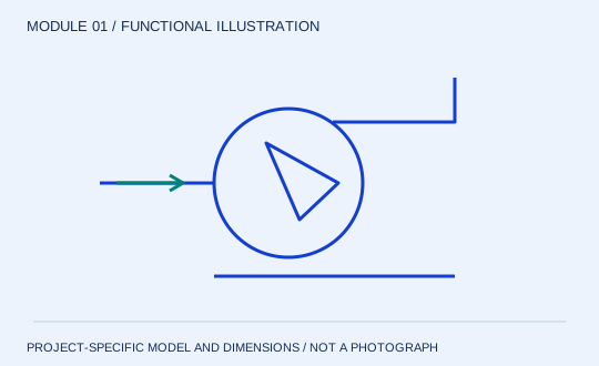
The circulation pump sets the flow through the heater. That flow is distinct from the incoming feed and from the mass of water evaporated. Selection must follow the concentrated liquid throughout the planned operating range, including start-up and restart after cooling.
Enquire about this moduleInput, output and connection boundary
| Input | Output | Interfaces |
|---|---|---|
| Recirculating liquid at separator pressure and current concentration | Liquid flow and pressure rise through the external heating circuit | Separator bottom, suction line, heater inlet, drive and seal services |
Specification inputs
| Parameter | Condition to state |
|---|---|
| Circulation flow | m³/h at stated temperature, density and viscosity; not feed kg/h. |
| Differential pressure | kPa across the specified loop, including heater, pipework, valves and fittings. |
| Power basis | Pump shaft demand, motor/VFD losses and operating efficiency stated separately. |
| Suction margin | Available suction conditions at actual liquid level, temperature and absolute pressure. |
Maintenance access
Provide access to the seal, coupling and wet end without dismantling unrelated equipment. Identify flushing or barrier requirements, wear parts and the isolation arrangement. Include the consequences of a pump trip in the cause-and-effect schedule.
Selection limit
A larger motor cannot make an unsuitable pump hydraulically or hygienically suitable. Particle passage, shear, abrasion and cavitation all need their own checks.