FORCED CIRCULATIONFOOD CONCENTRATION SYSTEMS

Home / Principle

The forced-circulation evaporation loop

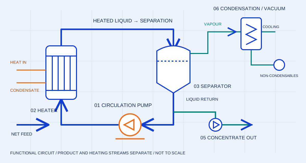
Pumping, heating and vapour separation have distinct jobs. Review them as a connected circuit.

Forced-circulation loop: separator liquid flows to the circulation pump, then through an external heater and back to the separator; vapour and concentrate leave on separate routes
Original simplified circuit • not to scale • not an equipment photograph

01 / CIRCULATION PUMP

Flow through the heater is a separate duty.

The circulation pump is selected against the concentrated product, loop pressure losses and suction conditions.

Inspect pump requirements →
01

Circulate liquid through an external heater

The pump maintains the process-liquid flow through the heating circuit. In the common non-boiling heater design, pressure is kept high enough to limit vapour generation in the heater. The returning liquid carries added heat toward the separation vessel.

02

Release vapour at the flash vessel

The separator operates at a lower pressure than the heated return. Part of the liquid flashes; vapour leaves through the overhead route while liquid remains in the circulating inventory. The vessel level affects separation volume and pump suction conditions.

03

Separate fresh feed, recirculation and withdrawal

Fresh feed replenishes the system and concentrated product is withdrawn at the required rate. The circulation flow may be much larger than either net stream. Do not label circulation-pump flow as feed capacity or evaporation capacity.

04

Review the entire circuit

Heater pressure drop, suction geometry, return location, vessel inventory and withdrawal controls all affect operation. Use a process flow diagram and a common duty sheet before comparing individual pump or heater quotations.
Related equipment

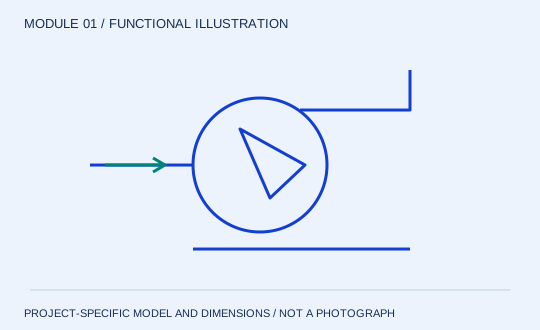
Circulation pump & drive functional diagram
MODULE 01

Circulation pump & drive

Keep the loop moving. The circulation pump sets the flow through the heater. That flow is distinct from the incoming feed and from the mass of water evaporated. Selection must follow the concentrated liquid throughout the planned operating range, including start-up and restart after cooling.

Review structure & specification →
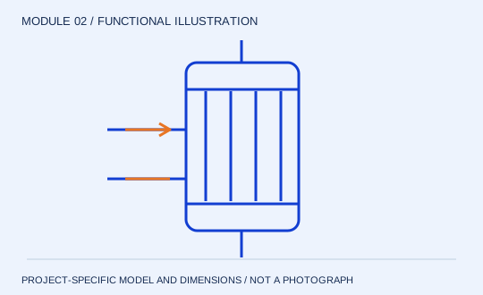
External heater functional diagram
MODULE 02

External heater

Add heat under pressure. In the common non-boiling heater arrangement, pressure in the circuit limits boiling within the heater. Heat is added before the liquid enters the flash zone. Tube or plate geometry is selected from product behaviour and pressure-drop constraints, rather than the circulation label alone.

Review structure & specification →
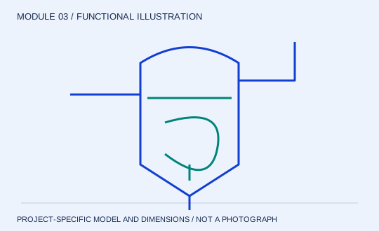
Flash separation vessel functional diagram
MODULE 03

Flash separation vessel

Release vapour and retain liquid. The pressure change at the separator enables part of the heated liquid to flash. The vessel provides space for vapour disengagement while maintaining liquid inventory for recirculation. Its level and geometry therefore affect both separation and pump suction.

Review structure & specification →

Next step

Continue the engineering review →