Home / Systems
Single-effect forced circulation evaporator
Evaluate a single heated circulation loop with separate flash separation, vacuum services and concentrate withdrawal for a defined product duty.
One effect, a complete equipment boundary
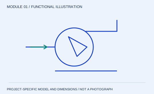
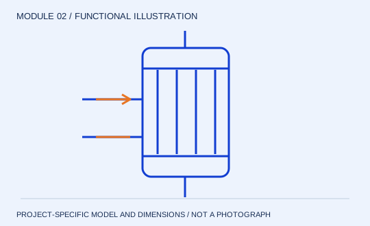
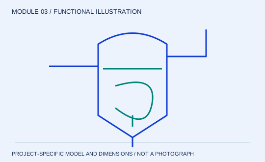
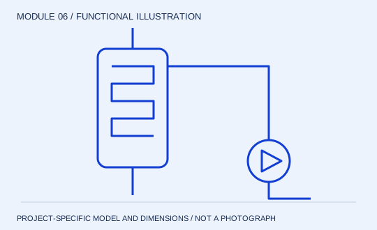
A single-effect arrangement combines a circulation pump, external heater and flash separator. Feed, concentrate, vapour and heating utilities remain separate streams. State whether the offer includes condensation, vacuum generation, controls and cleaning connections; a heater-and-vessel price does not describe the complete system.
When to compare this arrangement
Use this configuration as a clear reference when comparing a stand-alone concentration step or a finishing duty. Check the operating range, product residence history and available heating service. The number of effects alone does not establish product suitability or operating cost.
Selection information
Provide feed and final mass solids, net water removal, available steam conditions and cooling service. Confirm the final-concentrate viscosity and withdrawal conditions. Request a common duty sheet with pump demand and utility consumption stated separately.
Information to include in your enquiry
- Feed and final concentration
- Required water removal
- Steam and cooling conditions
- Product viscosity and quality limits